If you have bought a kit from us on day one: There seem to be a few missing resistors, ping @test47:matrix.org or come by to get them. Sorry!
This is a badge we created for the 39C3. The main idea was to create a badge which can be easily reconfiured and changed for different use cases. So.... let us present you thee (drumroll): Cyberwatch! A cyberpunk smartwatch you can solder yourself!
While searching for a solution, we found out that PCBs and standart SD Cards more or less have the same thickness. Born was the idea of using SD Card readers as a fast and easy way to add different PCBs and functionality to a motherboard.
During our time tinkering with the design, we ended up reducing the size of the motherboard, to be able to add the daughter boards in the design and being able to get them produced together in one go from the manufacturer. And it started to look like a smartwatch, so we decided to name it "Cyberwatch", being the big cyberpunk fans we are. Of course the daughter boards could only be named "shards".
Right now, there are two types of daughter boards available:
We strongly recommend reading this whole tutorial first before you start soldering. Of course, this is just text, so it cannot stop you.
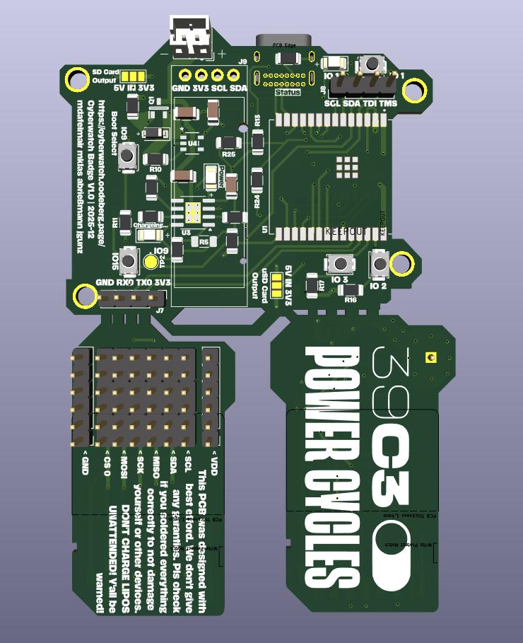
First, start by opening the component placement guide in a second window/tab and use it as guidance during the process.
Since we had to move some components closely together, we recommend a specific order in which you should solder the parts, especially if you haven't soldered much SMD before:
Start with the front side. You can mostly follow the enumeration of the parts from the component placement guide here. Since everything is quite tightly packed, some complicated parts like the charging controller IC or the battery disconnect transistor should be placed a bit earlier than the surrounding components.
The backside contains much fewer parts than the front. With the ESP soldered in place, it can be easily done after the front. R20 under the display is intentionally left empty. Solder the display LAST! And, if possible, place a small stripe of sticky tape under it to prevent shorts. Kapton tape is ideal, regular duck tape will do just fine.
Regarding the LED on the back: We recommend that you solder the LED sideways, facing the USB connector, for maximum indirect lighting effect. You can also solder it normally, but the effect will then need the Board to be placed on a suitable surface. Also, we recommend you use one of the white LEDs, but you can of course divert from that.
Regarding solder bridges: There are three (four including the LoRa shard) solder bridges on the board. Two are on the front, labeled "uSD Card Output" and "SD Card Output". Those control the voltage send to the SD card slots, in case you have a project that needs more voltage. For compatibility with regular SD cards as well as the LoRa shield, connect the center pad with the 3.3V one. WARNING: Unless you have a good reason why you want 5V, leave them at 3.3V! Otherwise you could break things! The other one on the back is necessary because for the LoRa board, we need more IO than we have pins. See the Meshtastic Readme for more info.
Call us at (DECT) 3203 for help and more info! If nobody picks up, send us a message at #cyberwatch39c3:matrix.org
There are ghosts in your circuits, and bugs in the solder? Don't worry, the schematic is available as PDF. If you need more info (or want to make your own changes), the full KiCAD source files are available as well.
The base cyberwatch firmware is coming soon (during the congress).
If you have soldered the optional LoRa shard, a fork of Meshtastic with instructions is available.
For news, updates and questions, join #cyberwatch39c3:matrix.org